| Selection of Roller Chain Drives |
| The following data should be taken into
consideration while selecting roller chain drives. |
a. Horsepower to be transmitted
b. RPM of the driving and driven sprocket (Speed ratio)
c. Load classification
d. Space limitations if any
e. Driven machine
f. Source of power |
| If the pitch centre distance and number of teeth
on both driving and driven sprockets are known, you can use the following
formula, tables and charts to calculate chain lengths. |
| Selection Procedure |
| For maximum service life, smooth operation and
optimum performance, the following points should be considered, while
determining the number of teeth in the pinion. |
| a) As most drives have an even number of pitches
in the chain, the use of a pinion with an odd number of teeth ensures even
distribution of chain and wheel tooth wear. |
|
b) Pinions for normal, steady
drives should generally not have less than 17 teeth, the reason being that
a chain forms a polygon around the pinion. When the pinion speed is
constant, the chain speed is subject to a regular cyclic variation. The
percentage of cyclic variation becomes less marked as the number of teeth
increases - and in fact becomes insignificant for the majority of
applications when the number of teeth in the pinion exceeds 17. |
| c) A minimum of 23 teeth is recommended on
moderate shock drives where the speed of the pinion exceeds 50 % of the
maximum rated speed, and for heavy shock drives where the speed of the
pinion exceeds 25% of the maximum rated speed. |
| d) The pinion should be heat treated to HV 10 -
550 for smooth drives where the pinion speeds exceeds 70 % of the maximum
speed and operates under full horsepower rating. For heavy shock drives,
the pinion should be treated in all cases. |
| Determine The Class of Load |
| If shock loads are expected, then first determine
the class of load on the basis of the drives equipment ( see table 1). |
|
Load Classifications |
|
Table 1 |
|
Uniform
Load |
Moderate
Shock Load |
Heavy
Shock Load |
|
Centrifugal pumps, Agitator for liquids, Conveyors, Fans- Uniform load |
Reciprocating pumps, Wood working M/c's Grinders, Conveyors- Irregular
load |
Presses, Earth moving equipment Shears, Cranes & Hoists,
Reciprocating and Shaker type conveyors, Crushers, Reciprocating feeders |
|
Generators, M/c’s all types with uniform non - reversing loads |
Mixers and Machines all types with moderate shock and non- reversing
loads |
Machines-all types with severe impact shock loads or variation and
reversing service |
Note : If table 1 does not list your equipment, go
by its similarity to a listed item
Establish The Design Horsepower
Establish the design horsepower by multiplying the
specified horsepower value with the service factor given in Table 2.
|
Service factor |
|
Table 2 |
| |
Type of Input Power |
|
Type of Driven |
Internal |
Electric |
Internal |
|
Load |
Combustion |
Motor or |
Combustion |
| |
Engine with |
Turbine |
Engine with |
| |
Hydraulic |
|
Mechanical |
| |
Drive |
|
Drive |
|
Uniform |
1.0 |
1.0 |
1.2 |
|
Moderate Shock |
1.2 |
1.3 |
1.4 |
|
Heavy Shock |
1.4 |
1.5 |
1.7 |
| Final Selection of Chain |
|
Selection of multi- strand chains
will become necessary if available space is limited or high speeds call
for a chain w i t h l o w e r p i t c h . The strand factors are given in
Table 3. To facilitate selection of multi-strand chains, multiply the
horsepower rating for single strand chains by the corresponding strand
factor. |
| ISO 10823 - 1996 standard of guidance can be
referred for selection of chain drive power. |
|
Multiple Strand Factor |
Table 3
|
|
No. of Strands |
Multiple Strand Factor |
|
2 |
|
1.7 |
|
3 |
|
2.5 |
|
4 |
|
3.3 |
|
5 |
|
3.9 |
|
6 |
|
4.6 |
|
8 |
|
6.2 |
|
10 |
|
7.5 |
|
Actual power = Input power x service factor x strand
factor.
|
|
Considering the actual power and rpm of the pinion,
using the horsepower rating chart select the chain for the application.
|
|
Select The Large Sprocket
|
|
By using the required shaft
speed ratio select the number of teeth in the large sprocket. If the required
shaft speed ratio cannot be obtained with a standard sprocket, increase the
number of teeth in the small sprocket by one or two, to obtain an acceptable
speed ratio with a slightly larger standard sprocket. The size of the large
sprocket is affected by the allowable wear elongation of the chain which may go
up to 3 %. The use of sprockets with more than 67 teeth reduces the life of the
chain expressed in percentage elongation as:
|
|
Permissible wear elongation = 200 / N ( %). The speed
ratio for a single drive should be not exceed 10:1 A greater ratio will make it
necessary to provide for two drives in series.
|
|
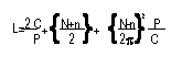
Determine Chain Length
|
|
Compute the length of chain required
using the formula given below. If possible, adjust the centre distance, so that
the length of chain required is always in an even number of pitches. For optimum
life of the chain and sprockets the centre distance between the two sprockets
should be 30 to 50 times the chain pitch.
|
|
Where L= Chain length in pitches
P= Chain Pitch
C=
Contemplated centre distance
N= Number of teeth on large sprocket
n= Number of
teeth on small sprocket |
|