|
I. General Information
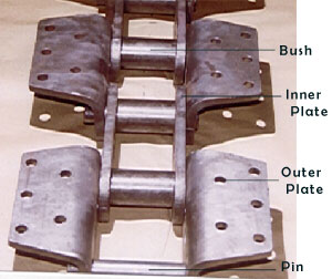
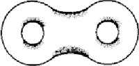
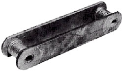
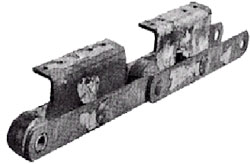
Chain Components
Chains normally consists of sidebars (Plate), pins, bushings
rollers & Connecting pins.
Plate
The plate is the component that bears the tension placed on the
chain. Usually this is a repeated loading, sometimes accompanied
by shock. Therefore, the plate must not only a great tensile
strength, but also must hold up to the dynamic forces of load and
shock. Further more, the plate must meet environment resistance
requirements.
Pin
The pin is subject to shearing and bending forces transmitted
by the plate. At the same time, it forms a load-bearing part,
together with the bushing, when the chain flexes during sprocket
engagement. Therefore, the pin needs high tensile and shear
strength, resistance to bending, and also must have sufficient
endurance against shock and wear.
Bushing
The bushing is subject to shearing and bending stresses
transmitted by the plate and roller, and also gets shock loads
when the chain engages the sprocket.
In addition, when the chain articulates, the inner surface
forms a load-bearing part together with a pin. The outer surface
also forms a load- bearing part with the roller’s inner surface
when the roller rotates on the rail or engages the sprocket.
Therefore, it must have great tensile strength against shearing
and be resistant to dynamic shock and wear.
Top
Roller
The roller is subject to impact load as it strikes the sprocket
teeth during the chain engagement with the sprocket. After
engagement, the roller changes its point of contact and balance.
It is held between the sprocket teeth and bushing, and moves on
the tooth face while receiving a compression load.
Furthermore, the roller’s inner surface constitutes a bearing
part together with the bushing’s outer surface when the roller
rotates on the rail. Therefore, it must be resistant to wear and
still have strength against shock, fatigue, and compression.
Cotter Pin, Spring Clip and T- Pin
These are the parts that prevent the outer plate from falling
off the pin at the point of connection.
Interference Fits at Chain Joints
Side bars of all chain are heat-treated for strength and wear
resistance. Bushings and pins are assembled to side bars with
controlled interference fits. These relatively heavy interference
fits provide a significant improvement in side bar fatigue
strength. As the pin interference fit increases, the side bar
fatigue strength increases. The optimized interference utilized in
TIDC chain was established by comprehensive fatigue testing.
Caution
Do not heat chain side bars or grind pins for ease in assembly.
Side bars fatigue may result and chain warranty will be void.
Fatigue Resistance
Fatigue resistance is critical in heavy duty bucket elevator
applications. These applications normally see high loads and
experience many load cycles in a very short time. Chains with low
fatigue strength will not stand up to this rigorous duty and will
break prior to normal chain replacement from wear.
Bucket Elevator Chain
A durable choice that keeps on working
TIDC Bucket Elevator Chains are specially designed to withstand
the severe demands placed on bucket elevators.
TIDC Bucket Elevator Chain is specially designed for
centrifugal discharge type bucket elevators. The ideal choice,
this chain has induction-hardened pins, case-hardened bushings,
and shot-peened link plates for superior fatigue strength and wear
resistance.
Top
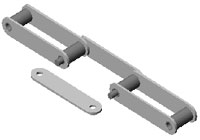
II. Assembly of Conveyor Chain
Unless otherwise specified, new conveyor chains are usually
supplied in 3m (10ft.) lengths to facilitate handling. The chain
is made in even numbers of pitches, with an inner link at one end
and an outer link at the other end, so they may be easily joined
together.
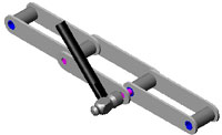
To connect the chain:
1. First fit the pinholes of the outer link plate to the
bushing holes to be connected and insert the pins.
Inserting
the Pins
2. Hold the counter plate with a hammer and tap the pin heads
with another hammer until the pins are completely inserted into
the link plate.
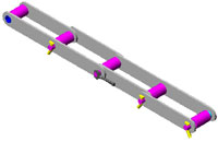
Putting on the Link Plate
3. Insert new T-pins or cotter pins into the bearing pins and
bend the ends to prevent loosening.
Inserting T-Pins or Cotter Pins
Note
Do Not Grind the Circumference of the Connector of the Side Bar
Hole to Ease Insertion of the Connector.
Do Not Heat Side Bars to Ease Pin Insertion. Side Bar Fatigue
may Result Which will Cause the Entire Chain and Bucket Assembly
to Fall into the Boot of the Elevator.
Top
III. Installation of the Chain
Before starting to install elevator chain, the foot shaft take
up should be positioned at its upper end of travel to provide for
maximum adjustment. To accomplish this, tie off the take up beam
assembled in the top of the boot section.
For convenience in shipping and handling, chains are coiled in
segments approximately 3 meters long. The chain can become twisted
if improperly handled.
Newer pick up the chain by hooking into the center of a coil.
Avoid This
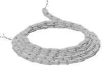
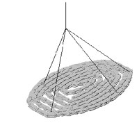
Support the entire coil.
Do This
Do not feed the chain into elevator on its side.
Avoid This
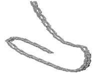
Do This
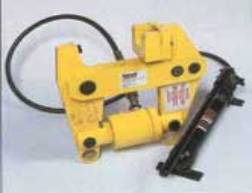
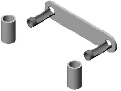
Assemble and disassemble chain quickly and safely
in the elevator with the portable
tool.
After the chain connection has been made, check to determine if
the joint is too tight, a sharp rap to the cotter end of the pin
with a hammer will aid in relieving the tightness. This can be
easily accompanied before buckets are attached.
The chain may now be installed in the elevator casing. The
chain lengths should be connected together outside the elevator
casing and fed in through the boot.
No more than 6 meters of chain should be connected together
outside of the elevator during installation, to avoid twisting or
bending. Be sure that the chain is oriented properly.
Top
Drop a line into the far-side of casing from the top. Using an
air tugger or other means available, feed chain around the bottom
of the foot wheel and upward to the top of the head wheel. At this
time, tie off the chain, making sure chain is secure. Repeat the
same procedure, feeding the chain upward on the opposite side of
the casing. Connect chain at the head wheel maintaining firm grip
on the chain while making connection. Return to the clean out door
and connect the chain. Make last chain connection in boot after
chain is installed.
Secure the chain in such a way, using a hoist for tying off to
a structural member laid across the bearing angle, so that there
is no chance of the chain running away and dropping into the boot.
Do not mount buckets to chain until the chain has been installed
in the elevator.
It is recommended that all elevators be equipped with a
positive stopping device. This feature will eliminate extensive
damage to the equipment by preventing a backward action of the
elevator.
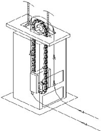
Chain Installation
Top
IV. Initial Start Up
1. Guards, access doors and covers must be securely fastened
before operating this equipment.
2. Electrical interlocks to warn personnel and shut off power
whenever discharge of elevator is interrupted.
3. Over load protection, Zero speed protection, Emergency stop
switch and all other interlock keep in working condition.
4. Be sure all debris, foreign objects and tools are removed
from the elevator inside and adjacent areas.
5. Confirm motor rotation. Ensure it is running in the right
direction.
6. Auxiliary equipment feeding the elevator must be electrically
interlocked with the elevator to prevent boot flooding when
elevator is not in operation.
7. Complete one or two revolution of the chain and buckets by
auxiliary drive or manual to check for proper assembly and
clearances. If no difficulties are experienced during auxiliary
drive rotation, run the elevator with out load for one hours .
V. Normal Operation
Before start up, make sure there is no obstruction to free
discharge of material.
Elevator should be started with empty buckets only. Starting
under load places undue strain on chain. Therefore, it is
imperative to allow all buckets to empty before stopping elevator.
Stop elevator only after feed has been stopped and elevator
allowed to discharge the material.
Successful operation of any elevator is dependent on con feed.
Material must be feed at a controlled rate within rated capacity
or boot will flood and stall elevator.
Avoid loading buckets to the extent of material spilling back
down into the boot section. Boot must not be allowed to pile up
with spilled material.
The operator(s) should become familiar with all aspects of the
construction and normal operating conditions of the equipments.
Thereby, immediately recognizing an abnormal situation or
operating condition before serious damage occurs
Top
VI.
Maintenance General
Special tools or equipment recommended to maintain or service
your elevator chain include a standard torque wrench, portable
jack and hammers to be used when checking.
Material should be centrally delivered at the specified uniform
rate. Avoid loading buckets to the extend that the material spills
back down into the boot section. The boot itself must not be
allowed to fill up with spilled material. Chain should be operated
at its rated speed.
VII. Chain Check Points
Chain life is generally considered to have expired when the
chain does not engage properly with the sprocket / Traction wheel
due to damage of its parts or elongation. The chain is usually
replaced when this occurs. A long working life without unexpected
trouble can be achieved if the chain is properly selected for the
conditions of its application. To help prevent premature wear or
damage, the following points should be checked.
Points to Observe
1. Abnormal Noise
2. Vibration of the chain
3. Chain rising on the sprocket / Traction wheel
4. Chain winding around the sprocket / Traction wheel
5. Stiff bending of chain, or links
6. Amount and condition of lubrication
7. Whether the chain contacts the case
8. Appearance of the chain. Check for dirt, corrosion, damage on
the outside surface of the roller, contact marks, etc. Also check
the inside and edge surfaces of the link plate and edge surface of the
pin.
9. Damage on the sprocket teeth / Traction wheel surfaces and
side surfaces of teeth and engaging area
10. Abrasive stretch of the chain
11. Bending of chain and rotation of roller
Check Points
1. Link Plate
If repeated loads in excess of the allowable load are applied
to the chain, there is a strong possibility of fatigue breakage
of the link plate. Fatigue breakage is difficult to anticipate
until a crack is produced. Usually a crack develops at the edge
of a hole or at the side of the link plate, as shown in the
illustrations below. The presence of cracks should be checked
carefully. Continuous checking can prevent accidents.
Top
Positions where cracks are likely to develop
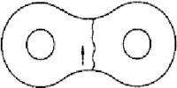
Example of an expanding crack
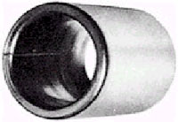
2. Roller
Care should be taken to avoid repeated impact loads over the
allowable load as fatigue breakage may occur. The roller should be
checked in the same way as the link plate. If foreign objects
interfere with the engagement of the roller and sprocket, the
roller may be damaged and a crack may develop. Careful attention
should be paid to this. Chains damaged due to fatigue breakage
must be completely replaced.
Crack produced on the roller
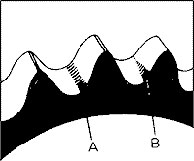
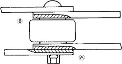
3. Sprocket
Chain and sprocket engagement can be checked by observing the
roller and tooth surfaces. The proper margin (A) and improper
margin (B) are shown in the fig. The installation should also be
checked. The normal area where wear will occur is slightly above
the bottom of the lowest point between the sprocket teeth. If
tension remains on the slack side, the roller will slightly touch
the lowest point between the sprocket teeth. When an idler or
tightener is used, wear will occur almost directly between the
sprocket teeth.
Areas to Check for Sprocket Wear
Top
VIII. Maintenance Check
Point
|
Check Points |
Comments |
|
Centering |
A high precision guide rail is essential to ensure proper
centering of the conveyor. If centering is not accurate
(with no side guide rail), the conveyor chain will wobble
and weave resulting in shorter conveyor chain life. |
|
Sprocket alignment |
When two or more sprockets are installed in a row, be
sure to align the position of the sprocket teeth. If the
sprocket teeth are not properly aligned, the working load
will not be equally divided and will cause the chain to
twist. |
|
Take-up |
If take-ups on both sides are uneven, the conveyor chain
will not engage smoothly with the sprocket. |
|
Initial chain tension |
Maintain adequate chain slack. If chain tension is too
high, loss of power will result. This is a dangerous
situation and if too loose, the chain will climb the
sprocket. |
|
Trial run |
An unloaded trial run should be conducted after
installation by switching the system on and off several
times intermittently. After inspection, continuous operation
may begin. |
|
Stopping the conveyor |
The conveyor should be stopped when it is not loaded,
otherwise the conveyed material may cause an overload when
the conveyor starts again. |
|
Lubrication |
Except for conveyor chain like the Flow Conveyor, which
runs without lubrication, conveyor chain should be
lubricated periodically. Lubrication of the reducer,
bearing, and driving roller chain is also essential. |
|
Securing conveyor parts |
Parts fastened to the conveyor such as buckets, aprons,
slates, etc. are apt to loosen due to vibration. Pay careful
attention to fastening nuts and bolts securely. Be sure to
check periodically. |
|
Amount of chain slack |
Regularly check and adjust the amount of chain slack. |
|
Temperature and prevention of freezing |
When differences in temperatures (summer and winter or
between day and night in the winter) are very severe,
conveyor damage may occur. Under these circumstances,
operate the conveyor carefully taking any variations in
temperature into account. |
|
Record of conveyor use and maintenance |
After installing the conveyor, prepare a record of the
expected capacity to be conveyed, the conveyor's speed, and
r.p.m. of the main shaft, electric current, voltage, working
hours, actual conveying capacity, inspection date,
lubricating date, details of trouble, etc. This will serve
as protection against unexpected accidents. This record will
also be convenient for maintenance and repairs. |
Top
IX. Preventive
Maintenance
Once the elevator is placed in operation, Preventive
maintenance program should begin.
1. The buckets should be checked periodically for loose bolts
and build up of material. All damaged buckets should either be
repaired or replaced to eliminate material falling into the boot.
2. Check the rubber lip or tongue plate on the discharge spout
of the elevator, which should not touch with the bucket.
3. Check take up of bucket clearance with bottom of boot.
4. Side bars inner surfaces should be checked for wear. This is
an indication of misalignment.
5. Loose or unseated pins are danger signals and could lead to
a sudden and unexpected chain shut down.
6. Excess material building in the chain and attachments could
cause improper seating on traction wheel rims / sprockets and
rough elevator operation.
7. Round parts in chain; that is, the pins and bushings should
be inspected for wear.
8. Traction wheel / Sprockets should be inspected for alignment
and excessive wear.
Weekly Inspection (once in 175 Hrs )
1. Check motor load.
2. Check bucket fixing bolt missing & looseness.
3. Check boot for material build up and clean.
4. Check material build up in chain components and hammer it so
that it can dislodge.
5. Check chain for connecting pin seating.
Quarterly Inspection ( once in 2000 Hrs )
In addition to weekly inspection points, following pointes are
to be checked
1. Check inside block links for wear
2. Check all side bars on bushing OD for wear.
3. Visually inspect clearance between each set of inner and
outer side bars. Excessive clearance suggests pin fracture.
4. Check for loose segmental fasteners. Check torque values for
segmental rim bolts.
5. Check segmental traction wheel unusual wear.
6. Check for loose or missing buckets.
7. Inspect and adjust tongue plate at discharge point for wear
and replace if excessively worn.
8. Check gravity take up guides and stop blocks; check for free
operation of take up guides, check for evidence of wear on guides.
Annual Inspection ( Once in 8000 Hrs )
In addition to weekly & Quarterly inspection points,
following pointes are to be checked.
a) Traction wheel / Sprocket
1. Check for loose or missing segmental fasteners and torque
values. If fasteners are missing, replace with proper diameter
high strength type.
2. Check for evidence of axial movement of sprocket along
shaft.
3. Check for evidence of unusual or excessive wear and replace
sets of segments as required.
b) Gravity Take up
1. Check stop blocks; check for free operation of take up in
guides; check for evidence of wear on guides.
c) Buckets
1. Check for loose or missing bucket fasteners.
2. Check for unusual wear patterns or damage buckets.
d) Drive station
1. Check head shaft bearings for evidence of wear.
2. Check foot shaft bearings and sleeves for evidence of wear.
e) Chain section
1. Check all side bars and bushing OD s for uneven or deep wear
patterns.
2. Check inside blocks for unequal wear from traction wheel /
Sprocket.
3. Check chain for missing T- pin.
4. Check for chain elongation wear.
5. Remove 5 or 10 pins at random and measure the pin OD and
bushing ID. Hammer test all pins for soundness.
Chain Tension
Adjustment of Chain Tension
The correct amount of chain slack is essential for proper
operation of the chain. When the chain is too tight, working parts
such as chain, sprocket wheel, shaft, bearing, etc. carry a much
heavier load. On the other hand, too much slack is also harmful
and causes the chain to climb the sprocket teeth.
Frequency of Adjustment
The chain has a tendency to stretch a certain amount at the
beginning of operation due to slight distortion of its component
parts. After such initial elongation, the chain stretches
slightly, but constantly, by normal wear. To maintain proper chain
tension, adjustments, if necessary, should be made at regular
intervals. Neglect of careful inspection increases the chance of
an accident.
Frequency of adjustment:
1st week - once a day
2nd ~ 4th week - twice a week
Thereafter - twice a month
Note:
The above frequency schedule is based on 8 hours operation a
day. When working hours are increased, the frequency of adjustment
should be increased accordingly.
Even Adjustment of Take -up on Both Sides
This can be easily accomplished when take-ups are cooperating
screw type or counterweight type. Where two parallel chains are
adjusted by two independently operated take-ups, care must be
taken to ensure even stroke on both the left and right side. An
uneven adjustment will cause the link plate and the side of the
sprocket teeth to interfere with each other and result in an
overload condition.
Chain Pitch Elongation
When the chain engages with the sprocket or runs on a curved
rail section, the chain flexes causing the chain to stretch. In
most cases, this is due to wear of the bearing parts such as the
pins and bushings. As chain pitch elongation increases, the chain
tends to climb the top of sprocket. This makes smooth operation of
the conveyor impossible. The limit of pitch elongation is
generally 2% - 6 % of the chain pitch.
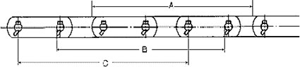
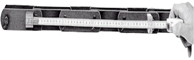
Places to Measure Chain Elongation
Fig. indicates the way to measure chain pitch. Using a steel
tape measure, measure as many pitches as possible (at least 4
pitches required). Measuring points should be properly determined
according to (A), (B) or (C) in Fig., depending on the wear
condition of the conveyor chain. The chain pitch elongation per
link is to be computed by comparing the actual pitch measured
against the original chain pitch.
Chain Pitch elongation can then be calculated.
|
Chain Elongation = |
Measured Length - Std. Length |
x 100(%) |
| |
Standard Length |
|
Standard Length = Chain Pitch x Number of Links
Note
When measuring, use at least 6 to 10 links to help keep any
measuring error to a minimum. When measurement cannot be done with
a vernier, it is possible, though less accurate, to use a tape
measure. If a tape measure is used, the measured length should be
as long as possible.
Top
X. Life of Chain and
Sprocket
After a certain period of time, wear will eventually appear on
the chain and sprocket. The life of conveyor chain depends on the
wear of each component part and on pitch elongation. Careful
inspection is required more often than for power transmission
roller chain.
The life of the conveyor chain component parts is shown below.
TIDC recommends that periodic inspections of the wearing parts are
conducted and that care be taken to ensure that proper maintenance
is carried out. Also, a schedule for changing the chains should be
established.
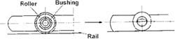
Roller Life
When wear between the rail, bushing and roller causes the under
surface of the link plate to contact the rail, the chain has
usually reached the end of its usability. As shown in Fig, when
the link plate starts contacting the rail, rolling contact
suddenly turns into sliding contact between the link plate and
rail, resulting in greater wear, an increase in chain tension and
a reduction in transmitted horsepower. Such wear generally appears
on horizontal or inclined apron conveyors, slat conveyors, etc.
Roller Wear
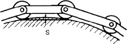
Where a curved section of rail is provided, the allowed wear
amount is decreased by a dimension equivalent to "S".
More care must be taken to observe wear than with horizontal
sections.
The chain life has expired as soon as holes or crevices appear
on the rollers due to wear.
Bushing Life
Bushings are generally useable until holes appear. Holes may
appear as a result of conveying very abrasive materials such as
iron ore powder, coke, etc.
Link Plate Life
Reciprocal friction between inner and outer link plates and
contact between side surfaces of rollers and inside surfaces of
link plates causes wear as indicated by (A) and (B) in Fig.
If the amount of wear exceeds 1/3 of the original plate
thickness, the tensile strength of the chain will be reduced. When
link plate wear appears faster than wear of other component parts,
misalignment of the conveyor during installation is the cause in
most cases. Misalignment can also develop during operation of the
conveyor. Therefore, careful inspection is required to ensure
maximum working life.
Please check the following items:
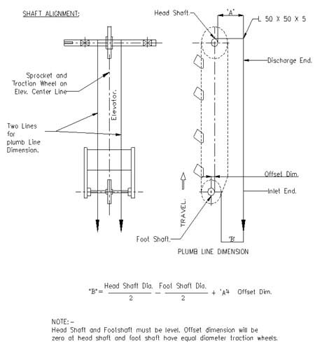
a. Correct alignment of driving and driven sprockets
b. Correct alignment of shafts in horizontal and vertical
planes
c. Preciseness of level gauge and accurate leveling
Sprocket Life
When the sprocket is worn, the chain tends to cling to the
sprockets and vibrate. The amount of allowable wear depends on the
conveyor type and chain size, but generally, wear to a depth of
3mm (0.12") to 6mm (0.24") is a sign that the existing
sprocket should be repaired or replaced with a new one to ensure
continued chain life. One of the following means may be used to
extend sprocket life:
a. Cut section (A) shown in Fig. with a grinder
b. Reverse the sprocket to change the engaging area of the
tooth
c. Surfacing can be made using a welding rod to obtain the
correct tooth profile. However, it is more effective to replace
the existing sprocket with a new one.
If the sprocket teeth are worn as shown in Fig. , the alignment
of the sprockets may be incorrect. Proper axial alignment of the
sprockets will help reduce or even eliminate this type of wear.
Sprocket wears
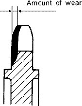
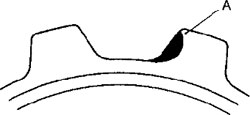
Fig. Sprocket Tooth Wear
Top
XI. Wear Characteristics
of Conveyor Chain
1. Mechanical wear
When conveyor chain is used under reasonable conditions and a
normal atmosphere, mechanical wear causes the bearing surface of
the chain to shine brightly. With proper lubrication, further life
can be assured.
Mechanical Wear
2. Wear caused by conveyed material
Material having excessive wear characteristics tends to stick
to the chain and to wear the surface of the chain due to
reciprocal friction between the material and chain. Under such
conditions, care should be taken to prevent material from falling
on the chain. For extra protection, chains should have higher wear
resistant specifications.
3. Wear due to corrosion
Conveyor chain used in applications where acidic or alkaline
chemicals are present, will be subject to corrosive wear as well
as mechanical wear. To protect against the chemical corrosion
accompanying mechanical wear, stainless steel is recommended.
Wear from corrosion
4. Electrochemical corrosion
When the chain is splashed with water, and then enters chemical
solutions, the surface of the sliding area (i.e., Pin/Bush,
Bush/Roller) is exposed to electrochemical corrosion, one of the
most damaging types of corrosion.
Electrochemical corrosion
Top
XII. Troubleshooting and
Problem Solving
|
Symptom |
Possible Causes |
Remeady |
|
Excessive wear at the inside of the chain’s link plates
or the teeth surface |
Improper centering of the sprocket |
Remove the chain and correct the centering of the drive
and driven sprockets |
| |
The chain is being pushed to the side |
Remove the cause of the push and/or install a guide
roller |
| |
Vibration caused by the inaccurate finishing of the
sprocket’s axle hole |
Check and correct the faulty locations and replace the
sprocket with a new part |
|
Improper flex or bending of the chain |
Rusting or corrosion |
Install a partition to protect the chain or select a
chain of suitable specification |
| |
Particles of the conveyed material have contaminated the
pin, roller, and bushings. Otherwise, contamination from
foreign particles. |
Install a partition to protect the chain. Select a chain
with large clearance between the pin, bushing and roller. |
| |
Deformation of the chain caused by improper installation |
Inspect and correct the installation of the sprockets and
axles |
| |
Inadequate lubrication |
Inspect the lubrication or look into wear resistant chain |
| |
Operation in extremely high temperatures ( Over 400 c ) |
Provide adequate clearance. |
| |
Seizure from excessive loads |
Provide periodic lubrication. Reduce load |
| |
Pin bending due to excessively high loading |
Reduce load. |
|
The chain is winding on the sprocket |
Too much slack in the chain. |
Adjust the chain length or distance between axles, or
install a tensioner. |
| |
Excessively worn sprocket. The chain and sprocket do not
match. |
Replace the chain and / or sprocket with a correct sized
part. |
|
The chain is climbing up on the sprocket |
The chain and sprocket do not match. |
Replace the chain and / or sprocket with a correct sized
part. |
| |
The total arc of contact with the chain on the sprocket
is insufficient. |
Have the total arc of contact be at least three teeth on
the sprocket |
| |
Excessive load. |
Reduce the load by installing a shock absorber |
| |
Inadequate back - tension |
Adjust the catenary or take up idler, or install a
tensioner |
| |
Excessive elongation of the chain due to wear |
Replace with a new chain |
| |
The distance between the center of the chain and sprocket
do not match |
Inspect and correct |
|
Unusual noises |
Inadequate lubrication to the connecting portions of the
pin and bushing |
Provide sufficient lubrication |
| |
Inadequate lubrication to the connecting portions of the
bushing and roller |
Provide sufficient lubrication. Use a bearing roller or
plastic roller |
| |
Winding or rising on the sprocket |
See previous symptom |
| |
Loose chain casing or axle bearing |
Tighten all nuts and bolts |
| |
Interference of the casing with the chain or other moving
part |
Inspect and correct |
| |
Excessive wear in the chain or sprocket |
Replace the chain or sprocket |
| |
Improper setting of the guide rail |
Inspect and correct |
|
Rusting of the chain |
Inappropriate selection of material |
Select a more suitable chain material. Protect the chain
from the environment. Apply a rust inhibitor |
| |
Condensation |
Eliminate the temperature difference between inside and
outside of the conveyor using insulation etc |
|
Improper roller spin and uneven roller wear |
Excessive load on roller |
Provide sufficient lubrication. Consider bearing roller |
| |
Particles of the conveyed material, or other foreign
particles, have gotten between bushing and roller |
Periodic cleaning. Install partition to protect chain |
| |
Particles of the conveyed material, or other foreign
particles, have build up on to the rail |
Periodic cleaning. Install partition to protect chain |
| |
The lubricant is falling on the roller surface and rail
with out entering between the bushing and roller, and
between the roller and link plate |
Select the appropriate lubricant and lubrication method |
| |
The bushing and roller have rusted together |
Select the appropriate specifications |
| |
The inner plate is moving sideward |
Replace with a new chain. Re inspect the installation and
load conditions |
| |
The bushing is cracked |
Reduce the load and lower the speed of rotation |
| |
The side surface of the roller is contacting the side of
the link plate due to a thrust load |
Eliminate the cause of the thrust load |
| |
The chain and sprocket do not match. Excessively worn
teeth |
Check for tooth deformation |
|
The roller is opening up |
Excessive load |
Reduce the load, provide adequate lubrication, remove any
large steps in the rail |
|
The roller or bushing is split (falling off ) |
Excessive load |
Reduce the load. Provide adequate lubrication. |
| |
The number of teeth is too few with respect to the
conveyor speed |
Increase the number of teeth. Decrease the speed |
|
The roller is becoming hour glass shaped |
Excessive load or inadequate lubrication |
Increase the lubrication, improve loading conditions, and
replace the chain with a new one |
| |
Excessively worn rail |
Correct or replace the rail |
|
The chain sticks and slips. (This can be caused by a
combination of many problems. Therefore, the listed remedies
may not solve the problem) |
Change the rolling friction coefficient of the chain |
Lubricate the chain and clean the rail. Change to a
bearing roller chain |
| |
The conveyor speed is too slow |
Increase the speed |
| |
Insufficient rigidity in the frame. The conveyor chain is
small compared to the device |
Increase the frame rigidity, increase the chain model
number. Decrease the slack in the drive roller chain |
| |
The force of friction is excessively large |
Lubricate the chain. Change to a bearing roller chain. |
| |
The machine is too long |
Divide the conveyor system into sections to decrease the
length |
| |
Inconsistent speeds due to movement along a polygon -
shaped path |
Use a 12 or more toothed drive sprocket |
|
Excessive wear of the sprocket teeth valleys and drive
sides |
Excessive worn teeth |
Replace both the chain and sprocket |
| |
Insufficient number of teeth |
Increase the number of teeth |
| |
Roller chain is not being used |
Use roller chain |
| |
The hardness of the teeth is insufficient with respect to
the load and conveyed material or foreign particles |
Use a sprocket with hardened teeth or changeable teeth |
| |
The Chain and sprocket do not match |
Replace the chain or sprocket with one that is of the
correct size |
|
Excessive wear of the inside link and pin on one side |
Increased internal tension when meshing with the sprocket |
Attach the supporting block to the sprocket. Reduce the
load. Lubricate the chain and sprocket. |
|
Sudden fracture of the link plate |
Excessive load |
Eliminate causes of the overloading. Install a safety
device ( fro example shock relay) Increase chain size |
| |
Weakening of chain caused by excessive wear of corrosion |
Replace with new part. Install a cover to protect the
chain. Periodically lubricate chain. Select a chain with the
proper specifications for the application. |
| |
The link plates are pressed outward by the sprocket |
Check and correct the installation. Excessively worn
chain or sprocket. Check the chain and sprocket match, and
correct as necessary. |
|
Crack in the link plate (1) fatigue breakage |
Excessive load or excessively large repetitive load |
Eliminate overloading or large repetitive loads |
| |
The factor of safety is not sufficient |
Increase the size or specifications of the chain to
increase the factor of safety. Replace with a new chain. |
| |
Repetitive load on attachment |
Eliminate overloading or large repetitive loads; Increase
the chain size to increase the allowable load of the
attachment. |
|
( 2 ) Corrosion stress crack. ( Bow shaped crack in heat
treated metal pieces ) |
The chain is being used in an acidic or alkaline
environment. ( This is not caused by a repetitive load ) |
Install a cover to protect the chain from the
environment. Replace with new part. Use a chain with a high
resistance to corrosion stress cracks. |
|
Deformed link plate holes and pin rotation ( the pin is
shifted from its normal position ) |
Excessive load |
Eliminate the cause of overloading and replace chain with
a larger size |
| |
Improper installation of the connecting link |
Replace connecting link with a new one. |
| |
Excessive load and inadequate lubrication |
Replace with a new chain and improve the lubrication and
loading conditions. |
| |
Seizure of the pin and bushing, improper bending or flex
of the chain |
Increase the chain size. Increase the clearance between
the pin and bushing. |
|
(1) Pin fatigue failure (2) Pin corrosive fatigue (3) Pin
brittle fracture (4)Pin sudden fracture |
The factor of safety used for calculation of the peak
load versus the breakage load was too small. The peak load
acted like a repetitive load on the chain. |
Recheck the size of the peak load, and eliminate its
cause. Replace the chain with a large pin diameter. |
| |
The pin was subjected to a tensile load at the side of
the fracture origin, where the break then progressed. Chain
is especially susceptible to this when the pin surface is
corroded and weak against bending stress. |
Recheck the size of the peak load, and eliminate its
cause. Replace the chain with a large pin diameter. Use a
pin of anti - corrosive material. |
| |
Poor environment |
Use an appropriate pin material |
| |
Excessive load |
Eliminate the cause of overloading, and replace chain
with a larger size. |
|
Excessive wear caused by the conveyed material. The
surface is worn away. |
The chain is exposed to acidic or alkaline substances,
and , therefore, more susceptible to machine wear, which
then progresses much faster. |
Prevent material from falling onto the chain. Use a wear
resistant chain. |
|
Excessive wear from corrosion. Link plates not made from
an anti corrosive material are corroding. |
The chain is exposed to acidic or alkaline substances,
and , therefore, more susceptible to machine wear, which
then progresses much faster. |
Use a material not affected by the chemicals. Use a wear
resistant material for the machine worn parts. |
|
Excessive wear from electro chemical corrosion. Only the
contact surfaces are worn. |
When the chain is covered with water or passes through a
solvent, the portions in contact suffer galvanic corrosion. |
Use a material not affected by the chemicals. Use a wear
resistant material for the machine worn parts. |
Top
XIII.
Safety Precautions
This Manual Contains Instructions for maintenance of TIDC
chains. The reliable operation and long service life of these
chains depends to a greater extend on the care taken during
installation and operation and the degree of maintenance.
Safety is a factor that must be considered at all times in the
operations and mechanical equipment. Use of proper tools and
methods can prevent serious accidents that may result in injury to
the operators and fellow workers.
Warning
Failure to Observe and Follow all Safety Instructions may
Result in Serious Personal Injury or Property Damage.
Use care to prevent injury, Comply with the following to avoid
serious personal injury
- Guards must be provided on all chain and sprocket
installations in accordance with provisions of ANSI/ASME B15.1
- 1992 "Safety Standards for Mechanical Power
Transmission Apparatus," and ANSI/ASME B20.1 - 1993
"Safety Standards for Conveyors and Related
Equipment," or other applicable safety standards. When
revisions of these standards are published, the updated
edition shall apply.
- Always lock out power switch before installing, removing,
lubricating or servicing a chain system.
- When connecting or disconnecting a chain:
a) Eye protection is required. Wear safety glasses, protective
clothing, gloves and safety shoes.
b) Support the chain to prevent uncontrolled movement of chain
and parts.
c) Use of pressing equipment is recommended. Tools must be in
good condition and properly used.
d) Determine correct direction for pin/rivet removal or
insertion.
e) Steady force, such as mechanical or hydraulic press, is
preferred. If impacting force such as hammer is used, take special
precautions to avoid metal chips from the chain or tools.
Chain Elongation History Card
|
Equipment Name |
|
|
Equipment Number |
|
|
Make |
|
|
Material Conveyed |
|
|
Capacity |
|
|
Conveyor Speed |
|
|
Drive Power Rating |
|
|
Drive power Actual |
|
|
Chain Model |
|
|
Installed On |
|
|
Pitch |
|
|
Sl # |
Date |
Drive End Pitch Measured |
Non Drive End Pitch Measured |
% Elongation |
Remarks |
|